


1×8 Fiber Cassette Splitter – Efficient Optical Signal Distribution
A 1×8 Fiber Cassette Splitter is a passive optical component used to distribute one incoming optical fiber signal across eight output paths. It is commonly used in fiber access networks where a single optical input needs to serve multiple downstream connections.
The cassette-style design is particularly useful for organized fiber installations because the splitter is enclosed inside a compact housing rather than leaving the internal optical components exposed.
For FTTH and PON deployments, choosing the correct splitter configuration is important because every additional splitting stage introduces optical loss. Therefore, the splitter should be selected according to the available optical power budget and the requirements of the complete network.
What is a 1×8 Fiber Cassette Splitter ?
A 1×8 Fiber Cassette Splitter has one optical input and eight optical outputs.
In a typical network arrangement:
OLT → Fiber Network → 1×8 Splitter → Multiple Subscriber/Distribution Paths
The incoming optical signal enters through the input side of the splitter and is distributed across eight output ports.
The splitter itself is a passive component, meaning it does not require a separate electrical power supply to perform optical splitting.
How Does a 1×8 Fiber Cassette Splitter Work?
The splitter receives an optical signal through its input fiber and divides the optical power among eight output paths.
For an ideal mathematical split, the available optical power is divided across eight outputs. However, a real-world splitter also has insertion loss and other optical losses, so the actual output power will not be exactly equal to the theoretical value.
This is why an ISP or fiber technician should calculate the complete optical power budget before selecting a splitter for an active FTTH or PON link. check saplliter only
Where is a 1×8 Fiber Cassette Splitter Used?
A 1×8 Fiber Cassette Splitter can be used in different parts of fiber access and distribution networks, depending on the network architecture.
Common applications include:
- FTTH networks
- GPON networks
- EPON networks
- FTTx deployments
- ISP distribution networks
- Fiber distribution boxes
- Fiber termination/distribution equipment
- Telecom fiber networks
- Building fiber distribution
- Residential fiber networks
- Commercial fiber installations
The exact installation point depends on the network topology and the optical budget available between the OLT and subscribers.
Why Use a 1×8 Splitter in an FTTH Network?
One major advantage of a 1×8 Fiber Splitter is that a single incoming optical fiber can be distributed to multiple downstream connections.
For example, an ISP may have one incoming fiber reaching a distribution location and need to distribute that optical signal toward several customer or distribution lines.
A 1×8 configuration provides eight output paths from one input, which can simplify fiber distribution while reducing the number of separate splitter units required.
However, the final subscriber count depends on the complete PON architecture, splitter arrangement and OLT/ONT optical specifications.
What is the Difference Between 1×8 Splitter and 1×8 Cassette Splitter?
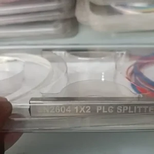
The basic optical function can be the same—splitting one optical input into eight outputs—but the cassette refers to the physical packaging/housing.
A cassette-style splitter provides a more organized form factor for installation inside compatible fiber management systems.
1×8 Fiber Splitter
Describes the optical splitting configuration.
1×8 Fiber Cassette Splitter
Describes both the 1×8 optical configuration and cassette-style housing.
Before ordering, customers should check the cassette dimensions, connector arrangement and compatibility with their particular enclosure.
How to Install a 1×8 Fiber Cassette Splitter?
Installation should be carried out by a trained fiber technician.
Step 1 – Identify the Input Fiber
Locate the optical fiber coming from the upstream side of the network, such as the OLT or preceding distribution point.
Step 2 – Connect the Input
Connect the incoming fiber to the splitter’s input according to the connector and fiber configuration of the supplied product.
Step 3 – Connect the Eight Outputs
Connect the eight output fibers to the required downstream fiber routes.
Step 4 – Manage the Fibers
Keep fiber routing organized and maintain the recommended bend radius. Avoid sharp bends, excessive pulling or unnecessary pressure on fiber cables.
Step 5 – Test the Optical Link
After installation, check the optical power and verify connectivity using suitable fiber testing equipment such as an optical power meter and, where required, an OTDR.
How to Test a 1×8 Fiber Splitter?
Testing should not be limited to simply checking whether light is present.
A proper installation may include:
- Visual inspection of connectors.
- Connector cleaning.
- Optical power measurement.
- Checking output paths individually.
- Checking insertion loss where required.
- OTDR testing when appropriate for the network.
- Verifying that the received optical power remains within the ONT/ONU operating range.
Dirty connectors can introduce significant additional loss, so connector cleaning should be performed before optical measurements.
What Should You Check Before Buying a 1×8 Fiber Cassette Splitter ?
Before purchasing, an ISP or installer should confirm the following:
- Split ratio/configuration
- Fiber type
- Operating wavelength
- Connector type
- Input/output connector arrangement
- Insertion loss
- Return loss
- Uniformity
- Operating temperature
- Cassette dimensions
- Compatibility with the intended enclosure
- Required optical budget
These specifications can vary between manufacturers and models, so the actual product datasheet should be used for final network planning.
1×8 Fiber Cassette Splitter for GPON and EPON
The 1×8 Fiber Cassette Splitter can be used in PON-based fiber access networks such as GPON and EPON when its optical specifications are compatible with the network.
In a typical PON deployment, the OLT sends the optical signal toward the distribution network. A passive splitter divides the signal so that multiple ONUs/ONTs can receive service.
The important point is that the splitter is only one part of the optical link. Fiber length, connectors, splices, adapters and other passive components also contribute to total optical loss.
How Many Customers Can a 1×8 Fiber Splitter Support?
A 1×8 splitter has eight output paths, but that does not automatically mean that every installation will support exactly eight active customers.
The actual subscriber capacity depends on:
- OLT port architecture
- PON technology
- Splitter topology
- Optical power budget
- ONT/ONU specifications
- Network design
- Required service reliability
- Additional splitters in the network
If an installation uses additional splitting stages, the total split ratio and optical loss must be calculated accordingly.
What Are the Benefits of a 1×8 Fiber Cassette Splitter?
Organized Fiber Management
The cassette-style housing helps keep the optical splitter assembly compact and organized.
1×8 Distribution
One incoming optical path can be distributed toward eight output paths.
Passive Operation
The optical splitter does not require electrical power for its splitting function.
FTTH Compatibility
It can be used as part of suitable FTTH and FTTx network architectures.
PON Network Applications
It can be incorporated into compatible GPON and EPON deployments.
Easy Network Expansion
A properly planned 1×8 distribution point can help organize multiple downstream fiber connections.
1×8 Fiber Cassette Splitter Technical Details
| Specification | Details |
|---|---|
| Product Type | Fiber Cassette Splitter |
| Configuration | 1×8 |
| Input | 1 |
| Outputs | 8 |
| Splitter Type | Passive Optical Splitter |
| Housing | Cassette Type |
| Color | Green |
| Applications | FTTH, FTTx, PON, Telecom |
| Network Use | GPON / EPON compatible applications |
| Installation | Fiber Distribution / Suitable Enclosures |
Note: Exact wavelength, insertion loss, return loss, fiber type, connector type, dimensions and operating temperature should be filled according to your actual product specification/datasheet.
1×8 Fiber Cassette Splitter vs Other Split Ratios
The correct splitter ratio depends on the network design.
| Splitter | Input | Outputs |
|---|---|---|
| 1×2 | 1 | 2 |
| 1×4 | 1 | 4 |
| 1×8 | 1 | 8 |
| 1×16 | 1 | 16 |
| 1×32 | 1 | 32 |
| 1×64 | 1 | 64 |
As the number of output paths increases, the theoretical splitting loss also increases. Therefore, a higher split ratio should only be selected when it fits within the available optical power budget.
Why Is Optical Power Budget Important With a 1×8 Splitter?
This is one of the most important considerations when installing a splitter in a live PON network.
The total optical loss of a connection is not caused by the splitter alone. It can include:
Fiber Loss + Splitter Loss + Connector Loss + Splice Loss + Other Passive Losses
The resulting optical power at the ONT/ONU must remain within the operating range specified by the relevant equipment.
Therefore, don’t select a splitter simply because its output count matches the number of customers. Always consider the complete optical link budget.
Who Can Use a 1×8 Fiber Cassette Splitter?
This product can be useful for:
- ISP owners
- FTTH installers
- Fiber technicians
- Telecom contractors
- Network maintenance teams
- Fiber optic distributors
- PON network installers
- Structured fiber network installers
It is especially useful when a compact cassette-style splitter is required for organized fiber distribution.
Reviews
There are no reviews yet.